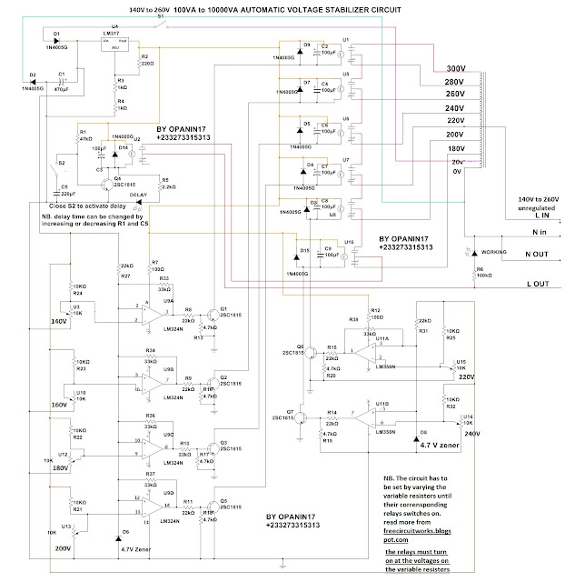
In this tutorial we are going to design an AC Voltage stabilizer using auto transformer. Auto transformer is a transformer with its primary and secondary connected together. This type of transformer is mostly used for AC voltage regulators (stabilizer).
100VA TO 10KVA POWER STABILIZER CIRCUIT
 |
| CLICK TO ENLARGE |
Circuit Explanation
The circuit above is a Voltage stabilizer circuit designed and tested by me. The circuit uses an auto transformer for voltage stabilization. It has same useful functions as stabilizers currently on our markets. It has built in Delay, delay indicator, working indicator and automatic switching.
The design accepts a wide range of input voltage ( 140V to 260V AC ). This does not mean that the circuit will fail when those voltage ranges are exceeded but its within these range that the AC voltage regulator will give constant 220V .
When power is applied to the unregulated input and S1 closed, Diodes D1 and D2 rectifies the 20V from the transformer and IC LM317 regulates its to 13V DC which is used to run the system. when the system starts working and the delay switch is closed, the output relay U2 will not switch until the delay time has passed. When delay time set by R1 and C5 is over, Q4 switches the output relay and the working indicator will now turn on to indicate working state.
To use the design for high power applications, use high current handling relays, else relay will fail.
HOW TO SET AUTOMATIC VOLTAGE REGULATION
Automatic regulation is done using LM324 and LM358 configures as voltage comparators. To configure the system to work automatically, use a variable AC of 140V to 240V and adjust the variable resistors until their corresponding relays turn on at the voltages written on the variable.
Another way is to use a variable supply AC supply of 12V to 25V AC. when using this method, set your supply to 21.8V and adjust the 240V variable until its relay turns on. Next, Adjust your variable supply to 20V and adjust 220V variable until its relay turns on. .....do the same for 200V at 18.1V, 180V at 16.4V, 160V at 14.5V and 140V at 12.7V AC.
Please connect your variable supply at the 20V point.
Another way of setting up the system is to use variable DC supply of 33V-15V DC and adjusting the variable resistors to turn the relay on. At 31V adjust 240V variable until it turn on, at 28V adjust 220V, at 25.5V adjust 200V, at 23.2 adjust 180V variable, at 20.5DC adjust 160V variable and at 18V adjust 140V variable.
Another way of setting up the system is to use variable DC supply of 33V-15V DC and adjusting the variable resistors to turn the relay on. At 31V adjust 240V variable until it turn on, at 28V adjust 220V, at 25.5V adjust 200V, at 23.2 adjust 180V variable, at 20.5DC adjust 160V variable and at 18V adjust 140V variable.
Professor How are you, you can clarify what the meaning of each U1 + U2 + U5 + U6 + U7 + U16, and is this electronic circuit actually practical ...
ReplyDeletehalmat kirkuki
U1 + U2 + U5 + U6 + U7 + U16 are relays.
Deletethis is the circuit you find in commercial home power stabilizers
i have been following your blog for quite sometime, and it has been educative. I have a problem with your relay, I dont know if thats how the software you use draws it, but it is confusing. I did not gt it at first. If you could switch to a more generic software with regular component symbols that is m0re comprehensible at first glance, I think it will be appreciated. Thanks. Keep up the good work Sir.
ReplyDeleteOk. Thanks very much. I will try and use a diff software
DeleteIt is a very clear and comprehensive tests settings procedure, simple and precise circuit design. Keep it up and more!
ReplyDelete