How to charge your phone using 12V battery or a 12V transformer.
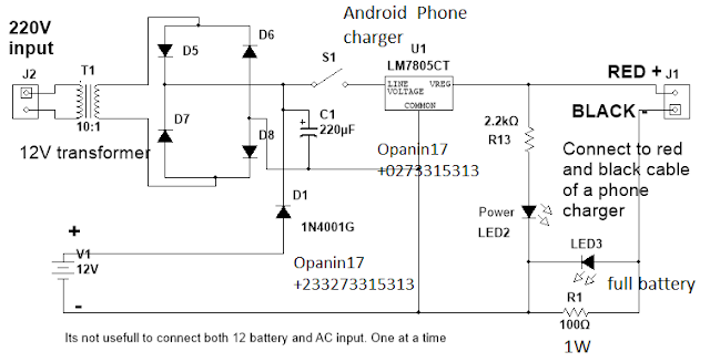
The circuit below shows a simple android charger or simple mobile phone charger using 12V battery or 12V transformer and few components which are also cheap and easy to get.
The circuit works by either using power from your house socket outlet or using any battery with voltage between 9V to 26V.
It is advisable not to use the two source of power together since it will be of no use.
When using a step down 12V transformer, the output voltage is rectified using D5, D6, D7 and D8. The rectified voltage is then then filtered using C1. After rectification, voltage of 12V to 18V DC will be obtained.
When S1 is closed, power flow from either the battery or the rectified voltage into U1 which is a 5V voltage regulator.
The function the 5V regulator LM7805 is to provide a constant 5V 1A current to our phone. but 1A is too high for our phone so we use 100ohms 1 watt resistor to reduce the current from 1A to a good level that will not harm our phone.
When there is power from LM7805, LED 2 turns on to indicate power.
During charging, LED 1 turns bright. As the phone battery gets full, LED 1 glows dim.
The function of D1 is to prevent rectified Voltage from going to the battery.
Connect the output of the circuit to the positive (red) and the negative (black) cables of any changer cable to start charging your phone.
The circuit below shows a simple android charger or simple mobile phone charger using 12V battery or 12V transformer and few components which are also cheap and easy to get.
CHARGE YOUR PHONE
USING 12V BATTERY PHONE CHARGER CIRCUIT
 |
| Click to view |
Circuit explanation
The circuit works by either using power from your house socket outlet or using any battery with voltage between 9V to 26V.
It is advisable not to use the two source of power together since it will be of no use.
When using a step down 12V transformer, the output voltage is rectified using D5, D6, D7 and D8. The rectified voltage is then then filtered using C1. After rectification, voltage of 12V to 18V DC will be obtained.
When S1 is closed, power flow from either the battery or the rectified voltage into U1 which is a 5V voltage regulator.
The function the 5V regulator LM7805 is to provide a constant 5V 1A current to our phone. but 1A is too high for our phone so we use 100ohms 1 watt resistor to reduce the current from 1A to a good level that will not harm our phone.
When there is power from LM7805, LED 2 turns on to indicate power.
During charging, LED 1 turns bright. As the phone battery gets full, LED 1 glows dim.
The function of D1 is to prevent rectified Voltage from going to the battery.
Connect the output of the circuit to the positive (red) and the negative (black) cables of any changer cable to start charging your phone.
Comments
Post a Comment
TYPE YOUR QUESTION OR COMMENT HERE