H Bridge circuit is the arrangement of electronic switches in a pattern that forms the letter ''H'' during switching. The switches may be bipolar transistors, Mosfets, IGBTs, etc.
These switches are controlled by logic signals in such a way that the four arranged switched connected in "H" turns on diagonally as shown below:
In H bridge circuit, never should two switches on the same side eg. A and C or B and D be turned on at the same time.
Turning A and B or C and D on at the same time will create a bombing sound and all your mosfets or transistor will produce beautiful smoke with a nice smell......Hahaha
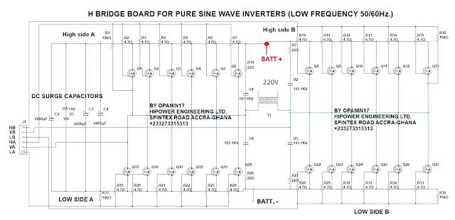
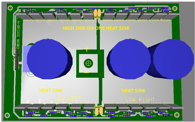
H bridge inverters are best for me especially when it comes to their way of charging your batteries until float level. The circuit below is an H bridge circuit which can handle 1000W to 3000W 12V, 1000W to 4000W 24V, 1000W to 5000W 48V.
Before you use any mosfet, please make sure your highest switching voltage is less than the maximum operating voltage of your mosfets by at least half.
Example 48V inverters should use at least 100V mosfets using 75V may result in failure.
These switches are controlled by logic signals in such a way that the four arranged switched connected in "H" turns on diagonally as shown below:
In H bridge circuit, never should two switches on the same side eg. A and C or B and D be turned on at the same time.
Turning A and B or C and D on at the same time will create a bombing sound and all your mosfets or transistor will produce beautiful smoke with a nice smell......Hahaha
H BRIDGE CIRCUIT FOR INVERTERS
In inverter systems, H bridges are mostly used for pure sine inverters with only few modified sine wave inverters using them.
H bridge inverters are best for me especially when it comes to their way of charging your batteries until float level. The circuit below is an H bridge circuit which can handle 1000W to 3000W 12V, 1000W to 4000W 24V, 1000W to 5000W 48V.
Before you use any mosfet, please make sure your highest switching voltage is less than the maximum operating voltage of your mosfets by at least half.
Example 48V inverters should use at least 100V mosfets using 75V may result in failure.
H BRIDGE DRIVER CIRCUIT
 |
| Click to View |
 |
| CLICK TO VIEW |
NB. without the addition of surge capacitors or not adding enough, your pure sine inverter will fail on inductive loads eg. fridges, air conditioners etc.
You can assume that 10000uf is for every 1000W.
There is something I omitted, that is a fast switching diode paralleled with a 47ohms resistor to feed the high sides and the low sides gates.
Connect this in series to the output of your driver stage before connecting it to this H bridge. Its another form of protection against failure.
Read more about this by clicking this link
http://manycircuits.blogspot.com/2017/05/mosfet-heating-solution-for-h-bridge.html
Read more about this by clicking this link
http://manycircuits.blogspot.com/2017/05/mosfet-heating-solution-for-h-bridge.html

Comments
Post a Comment
TYPE YOUR QUESTION OR COMMENT HERE