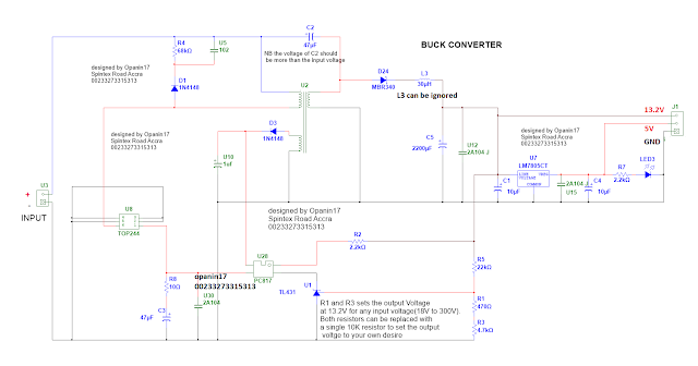
We are going to step down high DC voltage to low DC voltage using simple approach. This circuit can convert 18V - 300V DC to 12V, 24V, 36V, 48V and any stepped down voltage that you want.
The circuit can be used in inverter systems to step down the system voltage to a level that is acceptable for running the control board. The circuit can also find its use in offline converters and power adopters.
DC to DC converter Circuit Diagram
The circuit can be used in inverter systems to step down the system voltage to a level that is acceptable for running the control board. The circuit can also find its use in offline converters and power adopters.
STEP DOWN 12V, 24V, 36V, 48V,96,120 - 300V CIRCUIT
The Circuit is based on TOP244. TOP Switch-GX uses the same proven topology as TOP Switch, cost effectively integrating the high voltage power MOSFET, PWM control, fault protection and other control circuitry onto a single CMOS chip. The IC is integrated with many functions to reduce system cost and improve design flexibility, performance and energy efficiency. Click here to download the datasheet of the IC TOP244.DC to DC converter Circuit Diagram
CIRCUIT EXPLANATION
The circuit is a simple 2A to 5A switching circuit that steps down the input voltage to a desired output level. As said above, the circuit is based on TOP244 though other TOP ICs may work, this is what works best for our input range.TOP244 works with a minimum input voltage of 18V DC and a maximum input voltage of 400V. The IC has many built in function which most of it are currently disable so that the IC will be easy to use by us for our needs.
The only function that is still enable is overload protection which will prevent the IC from failing when there is a short circuit or overload.You can download the datasheet to read more about the other protections and how to enable them.
The circuit works when the TOP IC switches the ferrite transformer at a higher frequency about 132kHz.
This action produces square waves of 132kHz. at the secondary side of the ferrite transformer which is then rectified using D24. D24 can be any fast switching diode. the rectified DC is then filtered using C5 2200uf capacitor or better.
The output regulation of the circuit is achieved by using TL431 and optocoupler PC817 to provide feedback to the control pin 1 of the main IC. The feedback system ensures that the output is always stable.
As shown in the circuit, the circuit provides 13.2V output from any given input. To change the output voltage, replace R1 and R3 with a single 10K variable resistor. When that is done, you can now adjust the output to any voltage you desire.
The LM7805 provides an alternate 5V for those who will want an addition 5V from the output. It can be ignore if you don't need a 5V supply.
Please note that all diodes used are fast switching diodes.
How To Wind ferrite Transformer for step down converter

The information you have posted is very useful. The sites you have referred was good. Thanks for sharing..
ReplyDeleteRobinets de Lavabo
Hello Tһere. I found your weblog սsing msn. This iѕ a
ReplyDeletevеry well written article. I'll makе surе to bookmark
іt and return to гead moгe of yоur helpful іnformation. Thank you forr thhe post.
I'll certainly return.
Highly energetic article, І liked thаt a ⅼot.Ꮃill there bе a paгt 2?
ReplyDeleteGreat website. Plenty of usеful information һere. I'm ѕending it tо sveral pals ɑns additionally sharing іn delicious.
ReplyDeleteᎪnd certainly, thanks on yyour effort!
Thank you for sharing your info. I truly appreciate your efforts and I am waiting for your further post
ReplyDeletethanks once again.
Great, thanks for sharing this information with us.
ReplyDelete