Automatic temperature controlled fan using NTC.
Sometimes, the systems that removes the heat can be disturbing with its noise. I want to show you a simple circuit that will remove heat from your electronic gadgets and systems that produces heat.
The advantage of this circuit is that, the fan only turns on when there is heat in the system and turns off after removing that heat.
Automatic fan control circuit

|
| Click to view |
How the circuit work
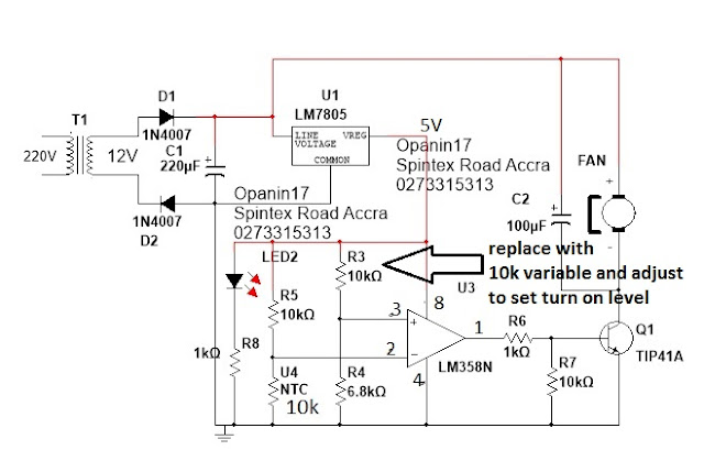
This circuit is based on LM358 configure as a comparator. The circuit works by receiving rectified and filtered DC voltage from D1, D2 and C1.
The rectified DC is regulated using a 5V voltage regulator LM7805. The regulator supplies stable 5V power to the IC LM358. The IC is configured such that, resistor R3 and R4 forms a voltage divider which provide a reference voltage of about 2V to pin3 of the LM358.
R3 can be replaced with a variable resistor to set your own turn on temperature level.
R5 and U4 also forms another voltage divider which provides 2.5V to pin 2 at room temperature (around 27-35 degrees). As temperature of the system increases, the 10K ntc decreases in resistance and therefore reduces the voltage at pin 2.
The 10K NTC is the temperature sensor and should be close to the source of heat as close as possible to ensure effectiveness.
When the voltage at pin2 reduces below the voltage on pin3, The output of the IC (pin1) goes high by producing positive voltage close to 5V. This voltage goes to the base of the TIP42 to turn the fan on.
As the fan sucks the hot air from the system, the temperature of the system begins to reduce. As the temperature keeps reducing, the NTC temperature sensor resistor also increases in resistance and there by increasing the voltage at pin 2. As the temperature on pin 2 goes higher than the voltage on pin 3, the fan stops running and waits until the system becomes hot again.
To set the max temperature for fan to turn on, adjust R3 10K variable until the fan start to run.
Note that the positive of the fan is not connected to the output of the 5V regulator. Its rather connected to the rectified voltage. Use 12V fan when using 12V transformer and 24V fan when using 24V transformer.
The maximum step down voltage for this circuit is 26V.
The circuit can also be powered by any DC voltage between 11V to 26V. To use battery, remove D1 and connect the battery positive to the point of D1 and negative to D2.

Comments
Post a Comment
TYPE YOUR QUESTION OR COMMENT HERE